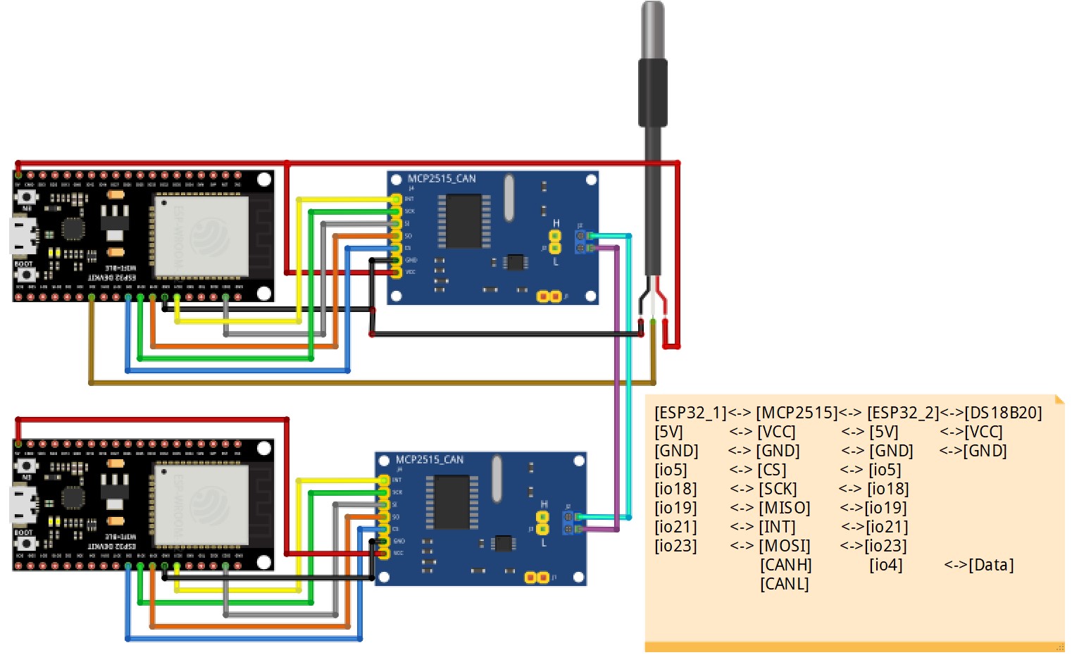
) in my channel to integrate into a new topic.One ESP32 transfer the temperature on DS18B20 to the other ESP32 via can bus system.
#1_ESP32+MCP2515+DS18B20 <--->#2_ESP32+MCP2515(ESP32 + MCP2515 use CanHacker on CAN Bus system)
#include <OneWire.h>
#include <DallasTemperature.h>
#include <BluetoothSerial.h>
#include <SPI.h>
#include "mcp_can.h"
//------CAN BUS setting ---------------------------------------------------------
#define CAN0_INT 21 // Set INT to pin 50
const int SPI_CS_PIN = 5;
MCP_CAN CAN0(SPI_CS_PIN);
//----- DS18B20 ------------------
#define DQ_Pin 4
OneWire oneWire(DQ_Pin);
DallasTemperature sensors(&oneWire);
byte data[12]; // buffer for data
byte address[8]; // 64 bit device address
#define LED_BUILTIN 2
BluetoothSerial SerialBT;
//--------- Flag structure --------------------------------------
typedef struct _vFlag
{
uint8_t BTFlag = 0;
uint8_t DC_Flag = 0;
uint8_t CANFlag = 0;
uint8_t I2C_Flag = 0;
uint8_t BMP180Flag = 0;
uint8_t DS18B20Flag = 0;
uint8_t JSONFlag = 0;
uint8_t LEDFlag = 1;
uint8_t sensor_Flag = 0;
uint8_t sensor1_Flag = 0;
uint8_t initial_Flag = 0;
uint8_t Tone_Flag = -1;
uint8_t IR_RECV_Flag=0;
uint8_t IR_SEND_Flag=0;
uint8_t FunctionFlag = 3;
uint8_t SendFlag = 0;
uint8_t BMPCnt = 0;
} vFlag;
vFlag *flag_Ptr;
vFlag flag;
//----------uart--------------
#define LINE_BUFFER_LENGTH 64
//--------- uart structure --------------------------------------
typedef struct _vUart
{
char c;
int lineIndex = 0;
int line1Index = 0;
int BTlineIndex = 0;
bool lineIsComment;
bool lineSemiColon;
//char *line;
char line[128];
//char line1[128];
char BTline[20];
//char R_line[20];
//char L_line[20];
String inputString;
String BTinputString;
String S1inputString;
int V[16];
char ctemp[30];
char I2C_Data[80];
int DC_Spped = 50;
float Voltage[16];
int Buffer[128];
int StartCnt = 0;
int ReadCnt = 0;
int sensorValue = 0;
} vUart;
vUart *Uart_Ptr;
vUart Uart;
//-------------CAN-------------------------------
typedef struct _vCAN_t
{
long unsigned int rxId;
long unsigned int txId;
unsigned char rxlen = 8;
unsigned char txlen = 8;
unsigned char rxext = 0;
unsigned char txext = 0;
unsigned char rxBuf[20];
byte data[8];
unsigned char masknum = 0;
unsigned char maskext = 0;
long unsigned int maskId;
unsigned char filternum = 0;
unsigned char filterext = 0;
long unsigned int filterId;
} vCAN_t;
vCAN_t *can_Ptr;
vCAN_t can;
//-------------------------------------------------
void setup()
{
Serial.begin(9600);
Serial.println(F("init"));
pinMode(LED_BUILTIN, OUTPUT);
SerialBT.begin("BT_BS18B20");// BTName
if (oneWire.search(address))
{
Serial.println("Slave device found!");
Serial.print("Device Address = ");
Serial.println(address[0]);
}
else
{
Serial.println("Slave device not found!");
}
//-----DS-----------
sensors.begin();
//standard frame
can.txId = 0x7D1;
can.txext = 0;
can.txlen = 8;
can.data[0] = 0x8E;
can.data[1] = 0x00;
can.data[2] = 0x00;
can.data[3] = 0x00;
can.data[4] = 0x00;
can.data[5] = 0x00;
can.data[6] = 0x00;
can.data[7] = 0x00;
}
//-----------------------------------------
void loop()
{
Serial.print(F("Main at core:"));
Serial.println(xPortGetCoreID());
while(1)
{
if(flag.LEDFlag == 1)
{
digitalWrite(LED_BUILTIN, HIGH); // turn the LED on (HIGH is the voltage level)
vTaskDelay(300);
digitalWrite(LED_BUILTIN, LOW); // turn the LED off by making the voltage LOW
vTaskDelay(300);
}
while (Serial.available() > 0)
{
Uart.c = Serial.read();
if ((Uart.c == '\n') || (Uart.c == '\r'))
{ // End of line reached
if (Uart.lineIndex > 0)
{ // Line is complete. Then execute!
Uart.line[Uart.lineIndex] = '\0'; // Terminate string
processCommand(Uart.line); // do something with the command
SerialBT.println(Uart.line);
Uart.lineIndex = 0;
Uart.inputString = "";
}
else
{
// Empty or comment line. Skip block.
}
Uart.lineIsComment = false;
Uart.lineSemiColon = false;
Serial.println(F("ok>"));
}
else
{
//Serial.println( c );
if ((Uart.lineIsComment) || (Uart.lineSemiColon))
{
if (Uart.c == ')')
Uart.lineIsComment = false; // End of comment. Resume line.
}
else
{
if (Uart.c == '/')
{ // Block delete not supported. Ignore character.
}
else if (Uart.c == '~')
{ // Enable comments flag and ignore all characters until ')' or EOL.
Uart.lineIsComment = true;
}
else if (Uart.c == ';')
{
Uart.lineSemiColon = true;
}
else if (Uart.lineIndex >= LINE_BUFFER_LENGTH - 1)
{
Serial.println("ERROR - lineBuffer overflow");
Uart.lineIsComment = false;
Uart.lineSemiColon = false;
}
else if (Uart.c >= 'a' && Uart.c <= 'z')
{ // Upcase lowercase
Uart.line[Uart.lineIndex] = Uart.c - 'a' + 'A';
Uart.lineIndex = Uart.lineIndex + 1;
Uart.inputString += (char)(Uart.c - 'a' + 'A');
}
else
{
Uart.line[Uart.lineIndex] = Uart.c;
Uart.lineIndex = Uart.lineIndex + 1;
Uart.inputString += Uart.c;
}
}
}
} //while (Serial.available() > 0)
while (SerialBT.available())
{
String BTdata = SerialBT.readString();
Serial.println(BTdata);
BTprocessCommand(BTdata);
}//while (BT.available())
if(flag.DS18B20Flag == 1)
{
vDS18B20Task();
sensors.requestTemperatures();
SerialBT.print("E");
SerialBT.println(sensors.getTempCByIndex(0));
}
if (flag.CANFlag == 1)
{
Serial.print("Temperatures --> ");
sensors.requestTemperatures();
Serial.println(sensors.getTempCByIndex(0));
//--------------------------------
float f=sensors.getTempCByIndex(0);
String mystring;
mystring = String(f);
byte float_data[mystring.length()+1];
mystring.getBytes(float_data, mystring.length()+1);
//---------------------------------------------
int size = sizeof(float_data);
for(int i=0;i<size;i++)
{
can.data[i] =float_data[i];
}
flag.CANFlag = 2;
flag.LEDFlag = 0;
delay(50);
byte sndStat = CAN0.sendMsgBuf(can.txId, can.txext, can.txlen, can.data);
if (sndStat == CAN_OK)
Serial.println("CAN Message Sent Successfully!");
else
Serial.println("Error Sending CAN Message...");
flag.CANFlag = 1;
}
/**
else
{
Serial.println("Open CAN First...");
}**/
}
}
//-------------------------------------
void BTprocessCommand(String data)
{
}
//----------------------------------------
void processCommand(char *data)
{
int len, xlen, ylen, zlen, alen;
int tempDIO;
String stemp;
len = Uart.inputString.length();
//---------------------------------------
if (strstr(data, "VER") != NULL)
{
Serial.println(F("ESP32_20230727"));
Serial.println(F("CAN_DS18B20"));
}
if (strstr(data, "DS18B20_ON") != NULL)
{
flag.DS18B20Flag = 1;
flag.LEDFlag=0;
Serial.println(F("DS18B20_ON"));
}
if (strstr(data, "DS18B20_OFF") != NULL)
{
flag.DS18B20Flag = 0;
flag.LEDFlag=1;
Serial.println(F("DS18B20_OFF"));
}
///----------CAN function ----------------
if (strstr(data, "CAN_ON_125") != NULL)
{
if (flag.CANFlag == 0)
{
if (CAN_OK != CAN0.begin(MCP_NORMAL, CAN_125KBPS, MCP_8MHZ))
{
Serial.println("CAN BUS Shield init fail");
Serial.println("Init CAN BUS Shield again");
flag.CANFlag = 0;
}
else
{
Serial.println("CAN BUS Shield init ok!");
CAN0.setMode(MCP_NORMAL); // Set operation mode to normal so the MCP2515 sends acks to received data.
pinMode(CAN0_INT, INPUT); // Configuring pin for /INT input
flag.CANFlag = 1;
Serial.println("init ok");
}
}
else if (flag.CANFlag == 2)
{
flag.CANFlag = 1;
Serial.println("CAN BUS message ON!");
}
}
if (strstr(data, "CAN_ON_250") != NULL)
{
if (flag.CANFlag == 0)
{
if (CAN_OK != CAN0.begin(MCP_NORMAL, CAN_250KBPS, MCP_8MHZ))
{
Serial.println("CAN BUS Shield init fail");
Serial.println("Init CAN BUS Shield again");
flag.CANFlag = 0;
}
else
{
Serial.println("CAN BUS Shield init ok!");
CAN0.setMode(MCP_NORMAL); // Set operation mode to normal so the MCP2515 sends acks to received data.
pinMode(CAN0_INT, INPUT); // Configuring pin for /INT input
flag.CANFlag = 1;
Serial.println("init ok");
}
}
else if (flag.CANFlag == 2)
{
flag.CANFlag = 1;
Serial.println("CAN BUS message ON!");
}
}
if (strstr(data, "CAN_ON_500") != NULL)
{
if (flag.CANFlag == 0)
{
if (CAN_OK != CAN0.begin(MCP_NORMAL, CAN_500KBPS, MCP_8MHZ))
{
Serial.println("CAN BUS Shield init fail");
Serial.println("Init CAN BUS Shield again");
flag.CANFlag = 0;
}
else
{
Serial.println("CAN BUS Shield init ok!");
CAN0.setMode(MCP_NORMAL); // Set operation mode to normal so the MCP2515 sends acks to received data.
pinMode(CAN0_INT, INPUT); // Configuring pin for /INT input
flag.CANFlag = 1;
Serial.println("init ok");
}
}
else if (flag.CANFlag == 2)
{
flag.CANFlag = 1;
Serial.println("CAN BUS message ON!");
}
}
if (strstr(data, "CAN_OFF") != NULL)
{
flag.CANFlag = 2;
flag.LEDFlag = 1;
Serial.println("CAN BUS message OFF!");
}
}
//-----------------------------------------
//-------------------------------------------
void vDS18B20Task()
{
Serial.print("Temperatures --> ");
sensors.requestTemperatures();
Serial.println(sensors.getTempCByIndex(0));
}